
Traeger Transceiver 5x5 100 watt
Serial Number 12280


Found this Traeger Transceiver 5x5 100 watt 12 volt transceiver down the Tip , i could not help myself , @ $2 , so now i am trying to get it on 80 meters maybe 40 meters later , it seems to work so far with a bit of this and that of dramas , a 10 channel capable radio with only 7 channel positions fitted and 5 channel strips installed , RFDS [royal flying doctor service] frequency's are there in the 5 slots , all i have to do is find some crystals for the bands i want .
It has a if of 1650khz or 1.65mhz , ie: for 80m 3650 i need a crystal of 3650 plus 1650 = 5300khz i think i have a 5300 lined up , but it will be USB as there is no LSB filter fitted as yet , i will be lookin about. And i have been lookin and found out that the early Codan 7727 series use the same IF and on the page was the fact that one can use low side injection instead of high side which results in a lsb output , so for 3650 minus 1650 results in a 2000khz (2meg) crystal , thanks that webpage i would not have thinky of that , now to find some cheepies i hope...Added later- Next day ,Well the 5300 crystal is turning out to be a 5272 (better still) =3.622mhz , ill be able to pull that to 3620 , as i have been looking at the channel strips more closely and if fitting 2 meg or below crystal they would need re-tuning and those ferrite slugs are bound to break also one would need to alter some capacitance too so me thinks it will be easier to find correct frequency mixer crystal and find a LSB crystal filter or even trip over a 5-5500 mhz vfo if i have to but the idea of a vfo annoys me just thinking about it , I WANT FIXED CHANNELS..........
I already fiddled and fitted a 4 pin mic socket as it had a din socket and sorted out a microphone which did not , and been all over it too... It draws only 200ma on receive at 13v with half volume with broken squelch which i thought was good for its day...
So looks like maybe i'll have to re get (pay for) the license again soon..........
Below pics-
Top left to right-- tune button , nb switch ,mute switch , channel knob , amber rf power light
Lower left to right-Red power on light [the glare] , emergency call button , green mute open light , a 200hz max clarifier , a spot for lsb/am/usb switch , on/off volume knob , non original mic socket


Below pics...Bottom side - if board with the USB filter , a vacant spot for a LSB filter there , also vacant lhs bottom is the spot for the mute board which is on the bench , band pass filter board on the left upper , PA at top.


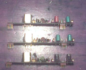
Below pics- Topside , 5 plug in channel strips with the crystals on them and the small noise blanker board also next to that should be the emergency call tone board which is also on the bench , and a closer look at channel strips , red led's indicate power there at the board , TL7805's 5v regulators all over the place , must be at least 10.


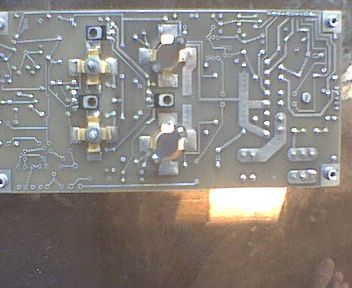
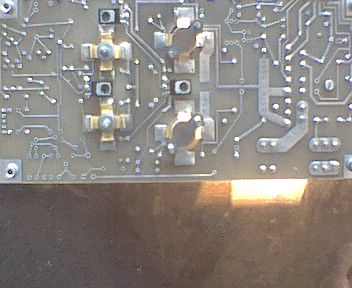
Below pics..band pass filter board relay switched , then the pa.


Below pic-Emergency Call Alarm tone board on the left , on the right is the SSB mute board which i think only breaks with a tone , i bin trying to get it to unmute , looks like it crook i find out later as i heard someone use the emergency call tone on 4980khz and it no worky at all , now i inside the mute board looking about .

added next day--Found the drama with the SSB mute , there was something shorting out the audio input to the mute board , i never actually saw what it was as it was in-behind and in-between the pins of the long blue sockets which the mute board plugs in to , a small needle poking around in there cleared it anyways , took me ages and a complete dismantle to find it .
That mute is a Audio derived system , not RF derived , and it works very well , with RF noise of guessing S4 -7 , the mute will not unmute but if any audio turns up even at S3 or even not understandable on the same frequency it will open up , me very happy with that mute now , and a crystal is turning up for a 80m band frequency -3620-.... yippy do doh ... AND i found the ALC , look out RF pa transistors .....
Anybody read this stuff and got schematics? i would like some , i want the see how protected the rx rf amp is , plenty lightning around here you know , but i probably draw it out anyways as usual.
Below Pics...The PA board..
Some routine maintenance on the Power Amp board after a clean up , replacing the electro's and a couple of 104 polyesters which have cracks and replacing the heat transfer paste on the transistors (DX541CF main and BLY89C drivers) which had long dried out , a few holes there not filled in with bits at the top LHS , from what i can see they are for AM biasing and protection , i take a guess.....


Added Later 2/1/07-- Some pictures of the channel strips/boards , looks like there are slightly different types depending on what frequency the Crystal is on i gather , the strip/board with the red and green coils is using a Crystal of 3.670mhz (2020 channel) the both green coil strip is 8.485mhz Crystal and both purple is 11.554mhz Crystal and there is also different size ceramics there too of a few picofarads on the strips AND guess what , the ferrite slugs move freely in all (i had to try it) , so now maybe i will be looking for some 2 and below MHz Crystals as breaking those slugs was a main criteria (not so fond memories of the old FT-200 slugs) .........But in typing that , still a pain to do , a new LSB Crystal filter is $80 maybe maybe maybe , But Radio cost $2 = not worth it.......


Added 10/4/07-more picture/descriptions soon as i bin fiddling more, its even got flash knobs now, no luck yet on a filter and bin busy sorting out the antenna ,a copy of a 40m Nvis but now a 80/40m trapped Nvis ..NEAR VERTICAL INCIDENCE SKYWAVE.
WORDS, PICTURES & PERMISSION BY:- PAUL GREGORY